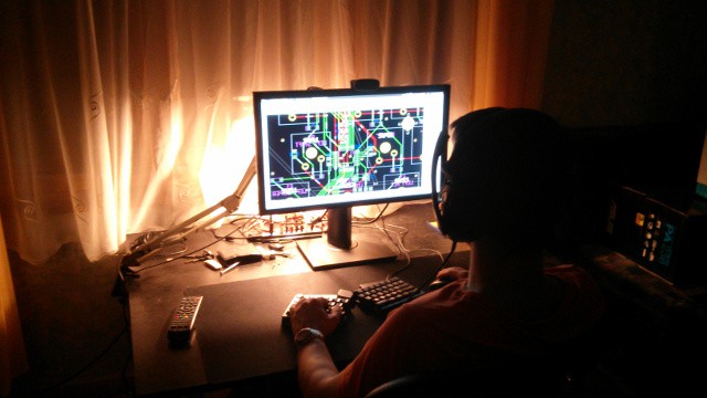
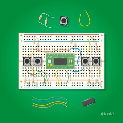
I've written a comprehensive article titled From the Ground Up: How I Built the Developer's Dream Keyboard. If you're interested about the internals of how a keyboard of this kind gets built then you're welcome to check it out. Thanks a ton for Toptal for featuring us!
We're happy to report that the PCA9634 IC that controls the columns of our LED display is now working as expected. This was a tricky case to solve so let us share the journey of finding the solution.
When starting to debug the problem it was rather strange that the Bus Pirate almost exclusively showed START and STOP bits but almost no actual payload. This shouldn't have happened because the I2C bus was clocked at 400kHz and the Bus Pirate should be able to decode 400kHz I2C communication because this very frequency can be selected from its menu. I still don't know what's wrong with my Bus Pirate but I ordered a new, more modern one which is on its way. Looking for alternative ways to track down the issue I broken out SDA and SCL, added a status LED to the board and reached for my Open Bench Logic Sniffer.
[fusion_builder_container hundred_percent="yes" overflow="visible"][fusion_builder_row][fusion_builder_column type="1_1" background_position="left top" background_color="" border_size="" border_color="" border_style="solid" spacing="yes" background_image="" background_repeat="no-repeat" padding="" margin_top="0px" margin_bottom="0px" class="" id="" animation_type="" animation_speed="0.3" animation_direction="left" hide_on_mobile="no" center_content="no" min_height="none"]
The signals that were analyzed by the sniffer were a mix and match. Sometimes the analyzed I2C communication made sense but other times it was riddled with protocol errors. Also, the strange thing was that I2C often hanged for some reason at which point I reached to the AVR freaks to help me. They suggested that I should not use I2C from an interrupt handler which I clearly shouldn't but this code has worked on an Arduino before so I knew this wasn't the core reason. It was time to switch to an Arduino to better able to debug the problem.
[/fusion_builder_column][fusion_builder_column type="1_1" background_position="left top" background_color="" border_size="" border_color="" border_style="solid" spacing="yes" background_image="" background_repeat="no-repeat" padding="" margin_top="0px" margin_bottom="0px" class="" id="" animation_type="" animation_speed="0.3" animation_direction="left" hide_on_mobile="no" center_content="no" min_height="none"]
Initially, I haven't had any 4.7K PTH resistors laying around for pulling up SDA and SCL but had some SMD ones so I made DIY PTH resistors by soldering wires to pads of 0805 SMD resistors. The sniffed signals were still full of protocol errors. I eventually managed to get PTH resistors which probably made my circuit more reliable but most importantly I realized that the 1Mhz sampling frequency that I used with the logic sniffer was barely sufficient to sniff the 400kHz I2C resulting in frequent decoding errors.
Documentation mentioned that the sampling frequency should be at least 10x larger than the frequency of the bus to be sniffed. After making the proper adjustment I was finally able to consistently see communication clearly, both inside and outside of the timer interrupt handler. That was the perfect moment to grab the working firmware and go back to the left keyboard half to test things there.
[/fusion_builder_column][fusion_builder_column type="1_1" background_position="left top" background_color="" border_size="" border_color="" border_style="solid" spacing="yes" background_image="" background_repeat="no-repeat" padding="" margin_top="0px" margin_bottom="0px" class="" id="" animation_type="" animation_speed="0.3" animation_direction="left" hide_on_mobile="no" center_content="no" min_height="none"]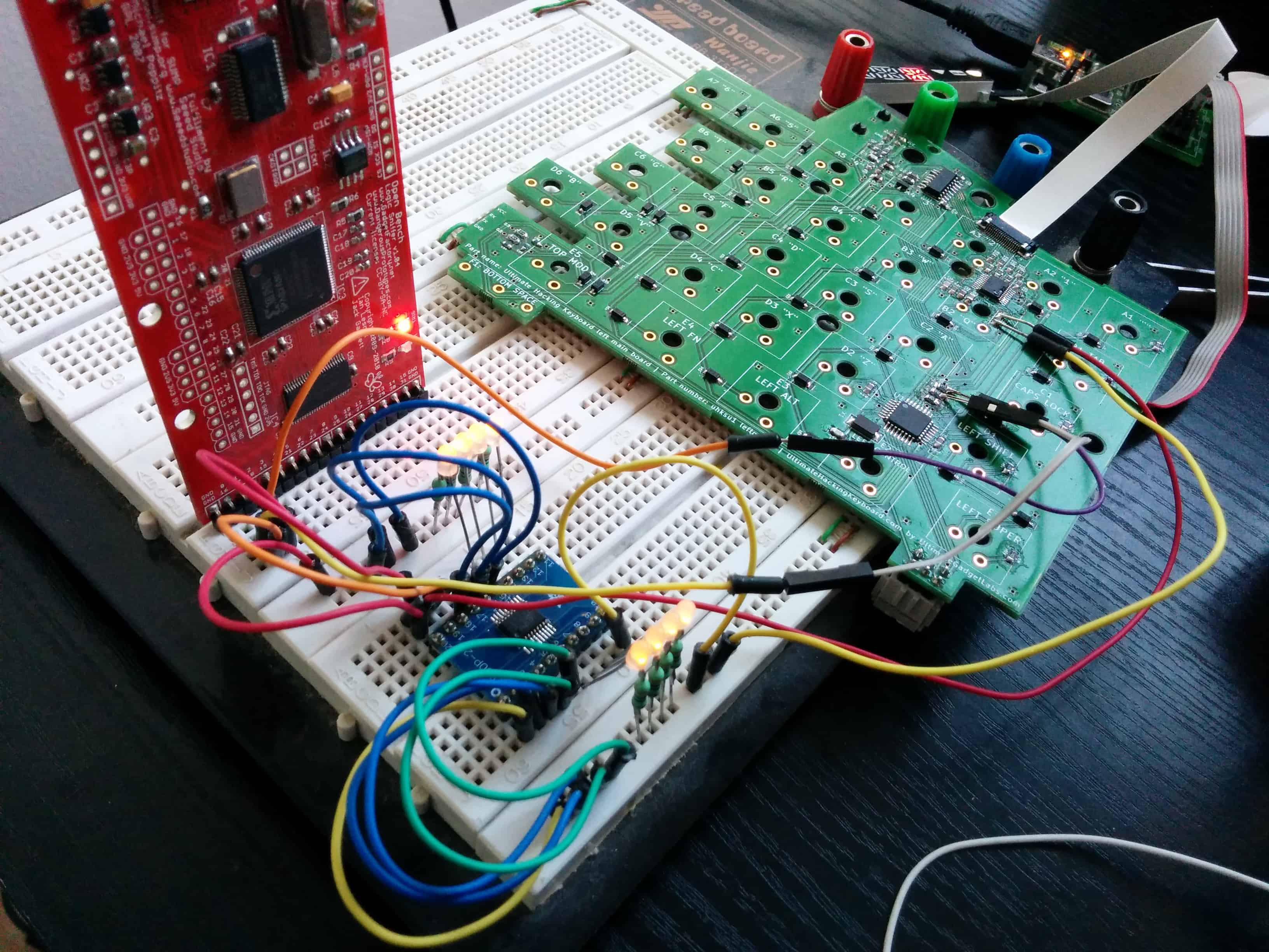
This time I broke out not only SDA and SCL but VCC and GND too to interface with an external PCA9634 that was soldered onto a breakout board. Even though initially I couldn't control the LEDs that were wired to the external PCA9634 but the sniffer showed me that that an ACK was received after sending the address of the PCA9634 which was very encouraging.
After messing around with the code I finally realized that there was a critical bug in it. I shifted the bits of the auto increment flags not by 5 bits as described by the PCA9634 data sheet, but by 4 bits! This resulted in sending invalid register numbers that didn't make the IC do anything useful. After fixing this issue the LEDs started to toggle as expected and the sniffed communication looked great, too.
[/fusion_builder_column][fusion_builder_column type="1_1" background_position="left top" background_color="" border_size="" border_color="" border_style="solid" spacing="yes" background_image="" background_repeat="no-repeat" padding="" margin_top="0px" margin_bottom="0px" class="" id="" animation_type="" animation_speed="0.3" animation_direction="left" hide_on_mobile="no" center_content="no" min_height="none"]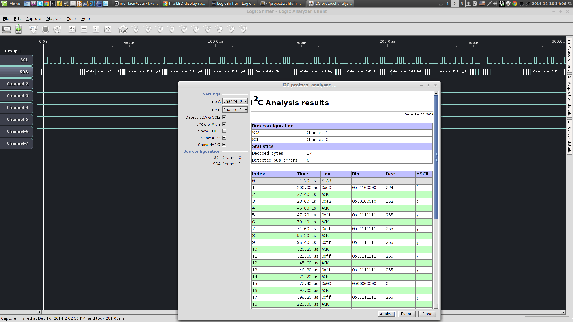
At this point both the external, broken out PCA9634 and the internal one was wired to the MCU but only the external was working. It was apparent that this is some sort of an electrical problem. My best idea was to connect the SDA, SCL, VCC, GND and OE lines of the external PCA9634 right to the pins of the on-board PCA9634 instead using the previously installed wires. By replacing the connections one by one I should be able to figure out which connection is the bad one.
Accessing the pins of the TSSOP packaged PCA9634 was rather hard, being merely 0.65mm away from each other. My only option was to use my wiring pen to solder enamel wires right to the pins of the on-board IC. Eventually, I managed to break out the connections right at the pins of the IC.
[/fusion_builder_column][fusion_builder_column type="1_1" background_position="left top" background_color="" border_size="" border_color="" border_style="solid" spacing="yes" background_image="" background_repeat="no-repeat" padding="" margin_top="0px" margin_bottom="0px" class="" id="" animation_type="" animation_speed="0.3" animation_direction="left" hide_on_mobile="no" center_content="no" min_height="none"]
[/fusion_builder_column][fusion_builder_column type="1_1" background_position="left top" background_color="" border_size="" border_color="" border_style="solid" spacing="yes" background_image="" background_repeat="no-repeat" padding="" margin_top="0px" margin_bottom="0px" class="" id="" animation_type="" animation_speed="0.3" animation_direction="left" hide_on_mobile="no" center_content="no" min_height="none"]
[/fusion_builder_column][fusion_builder_column type="1_1" background_position="left top" background_color="" border_size="" border_color="" border_style="solid" spacing="yes" background_image="" background_repeat="no-repeat" padding="" margin_top="0px" margin_bottom="0px" class="" id="" animation_type="" animation_speed="0.3" animation_direction="left" hide_on_mobile="no" center_content="no" min_height="none"]
[/fusion_builder_column][fusion_builder_column type="1_1" background_position="left top" background_color="" border_size="" border_color="" border_style="solid" spacing="yes" background_image="" background_repeat="no-repeat" padding="" margin_top="0px" margin_bottom="0px" class="" id="" animation_type="" animation_speed="0.3" animation_direction="left" hide_on_mobile="no" center_content="no" min_height="none"]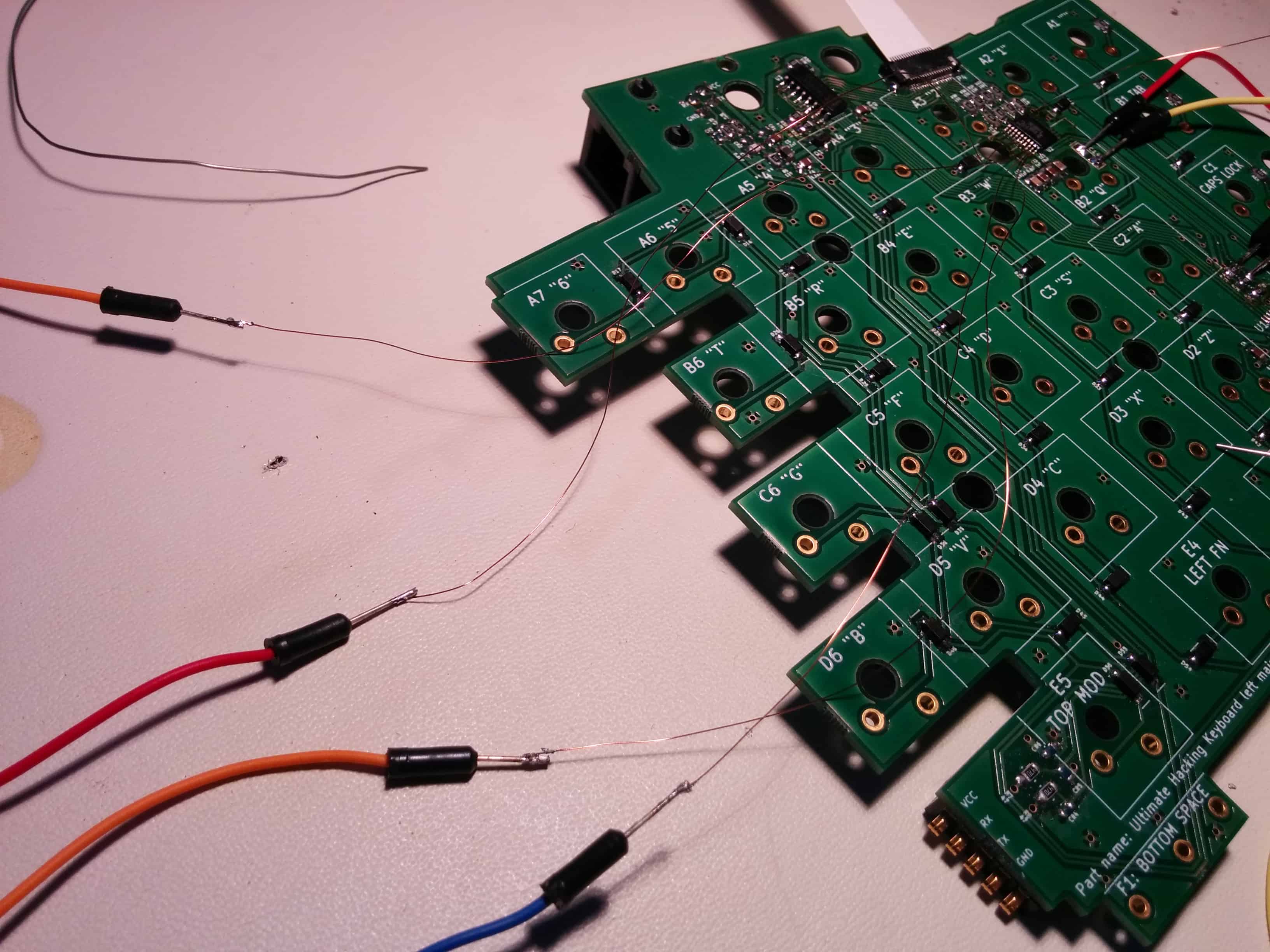
When powering up the board something unexpected happened: the on-board PCA9634 immediately started working! This was rather strange because I previously did continuity tests with my multimeter and based on those all connections were flawless. I guess there was a soldering error which I couldn't notice because when I pressed down the pin with the multimeter probe it must have connected to the pad beneath it and when I released the probe the pin must have gone back to its disconnected state in a spring-like fashion.
As a software developer these kinds of debugging scenarios really make me appreciate the relative simplicity of software. Not that software isn't a complex beast in itself but when being coupled with hardware issues like the above it can really be a little too stressful. But no problem; it's the nature of the beast and chances are it will never be any easier. At the end of the day challenges like this make the triumph even sweeter.
Wanna see some more photos? Head over to the photo album![/fusion_builder_column][/fusion_builder_row][/fusion_builder_container]
SMD components have been surface-mounted onto the 4th generation PCBs. The firmwares have yet to be uploaded and the switches to be soldered. This is coming together...
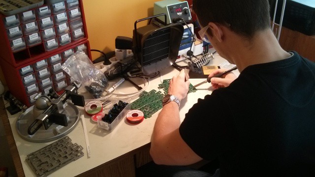
We're about to heat up the soldering iron and bring this beast to life! Yay!

András has just became ready with the stainless steel plates of our 4th generation prototype. The purpose of these plates is threefold:
Unlike the previous versions, this version of the plate contains the two half holes that enable the permament interconnection of the two keyboards halves.
[fusion_builder_container hundred_percent="yes" overflow="visible"][fusion_builder_row][fusion_builder_column type="1_1" background_position="left top" background_color="" border_size="" border_color="" border_style="solid" spacing="yes" background_image="" background_repeat="no-repeat" padding="" margin_top="0px" margin_bottom="0px" class="" id="" animation_type="" animation_speed="0.3" animation_direction="left" hide_on_mobile="no" center_content="no" min_height="none"]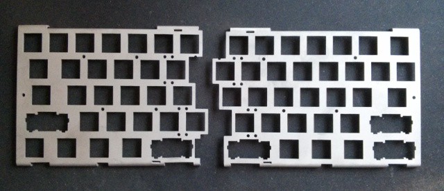
[/fusion_builder_column][/fusion_builder_row][/fusion_builder_container]
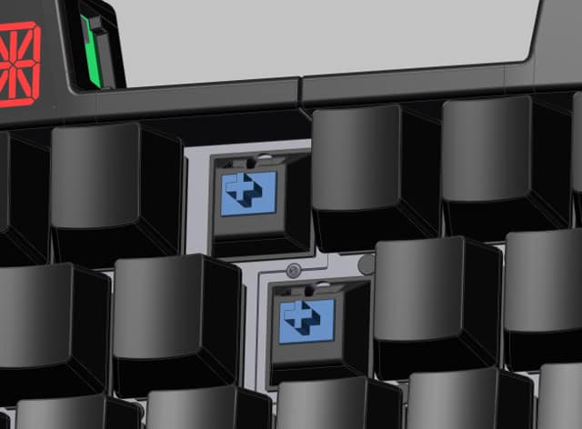
We foresee the UHK to be mainly used in a split fashion and expect people to use it merged almost exclusively for transportation purposes.
That being said, despite of our assumptions there may be a number of people who might want use it in a merged state all the time. The magnets that hold the two keyboard halves together are pretty strong but still the halves can come apart occasionally. To address this scenario András, mechanical engineer extraordinaire has come up with a way to permamently interconnect the halves. The beauty of his design is that all it takes is screwing a single screw.
People say that a picture says more than a thousand words and we have not one but four pictures that show you our design.
Labelling the keycaps of our 4th generation prototype was like many other: it's critical to know about the right technology for the job. After talking to a super-knowledgable guy it was a matter of sending over some files to a company, spending some hard-earned cash and waiting a little while. Then András had to precisely position the labels and transfer them to the blank keycaps which he did marvelously.

Just to avoid any misunderstanding, a blank version is planned so fear not!
We're nearly finished with the 4th generation prototype that will feature more powerful microprocessors and probably most importantly will be able to drive our new, snazzy LED display! Yay!
[fusion_builder_container hundred_percent="yes" overflow="visible"][fusion_builder_row][fusion_builder_column type="1_1" background_position="left top" background_color="" border_size="" border_color="" border_style="solid" spacing="yes" background_image="" background_repeat="no-repeat" padding="" margin_top="0px" margin_bottom="0px" class="" id="" animation_type="" animation_speed="0.3" animation_direction="left" hide_on_mobile="no" center_content="no" min_height="none"]